Company

  • MSR Electronics GmbH

Mounting Instructions Data Loggers

Mounting recommendation for MSR shock and vibration data loggers

Proper mounting of the data loggers is essential for the correct measurement of dynamic loads. Before starting data recording, verify that the data loggers have been mounted correctly. The MSR data loggers should be firmly attached as close as possible to the object to be monitored, preferably directly to the object itself. Mounting the data logger on the packaging or on the transport vehicle may lead to deviating measurement results. Secure the data loggers to the object using the designated mounting holes. Alternatively, the data loggers may be secured using strong magnets or high strength industrial adhesive tape.
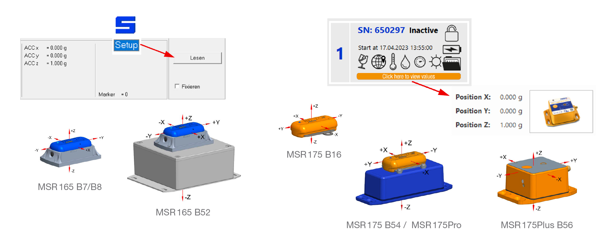
Orientation

Align the axes of the data loggers with the main directions of movement. The data loggers can be mounted in any position. Make a note of the position and direction of the axes for later evaluation.

Determining the inclination

In the MSR 175, MSR 175Plus, and MSR 175Pro models, the accelerometer measures gravitational acceleration directed toward the center of the Earth (0 ≤ X, Y, Z ≤ ±1 g). The inclination angle of the data logger can therefore be determined approximately using trigonometric functions describing rotation about a single axis within a range of 0 to ±180°.

Example: ACC x = -0.518 g, ACC y=0.425 g, ACC z=0.741 g

1) The measured gravitational acceleration alone is not sufficient to uniquely determine the rotation angle.

Housing types: Outlines, mounting hole patterns, screw fixings

Housing types Outlines, Hole patterns Screw fixings
MSR165 B7/B8Shock and vibration data logger MSR165, housing type B7 / B8 Umriss/Bohrbild Datenlogger MSR165, Gehäusetyp B7/B8 Thread assembly: e.g. DIN 965A / ISO 7046 A2 M3x8
Tightening torque: 0.45-0.55 NmMounting in wood and sheet metal: e.g. DIN 7983C / ISO 7051 A2 2.9×19
Tightening torque: 0.4-0.5 Nm
MSR175 B16MSR175 transport data logger, housing type B16 Umriss/Bohrbild Datenlogger MSR175, Gehäusetyp B16 Thread assembly: e.g. DIN 7085A / ISO 7045 A2 M6x12 Tightening torque: 4.5-5.0 Nm

Mounting in wood and sheet metal: e.g, DIN 7981C / ISO 7049 A2 5.5×19
Tightening torque: 4.0-4.5 Nm

MSR165 B52


Shock and vibration data logger MSR165, housing type B52

Umriss/Bohrbild Datenlogger MSR165, Gehäusetyp B52 Thread assembly: e.g. DIN 7085A / ISO 7045 A2 M4x10 Tightening torque: 1.2-1.4 Nm

Mounting in wood and sheet metal: e.g. DIN 7981C / ISO 7049 A2 5.5×19
Tightening torque: 1.0-1.2 Nm


MSR175 B54 / MSR175ProMSR175Pro transport shock monitoring data Logger for heavy-load and transformer shipments Umriss/Bohrbild Datenlogger MSR175, Gehäusetyp B54 Thread assembly: e.g. DIN 7085A / ISO 7045 A2 M4x10 Tightening torque: 1.2-1.4 Nm

Mounting in wood and sheet metal: e.g. DIN 7981C / ISO 7049 A2 5.5×19
Tightening torque: 1.0-1.2 Nm

MSR175Plus B56 1)MSR175plus transport data logger, housing type B56
Umriss/Bohrbild Datenlogger MSR175plus, Gehäusetyp B56 Thread assembly: e.g. DIN 965A / ISO 7046 A2 M4x12
Tightening torque: 1.2-1.4 NmMounting in wood and sheet metal: e.g. DIN 7983C / ISO 7051 A2 3.5×19
Tightening torque: 1.0-1.2 Nm

1) The GPS antenna of data logger MSR 175Plus, (housing type B56) should be attached to the outside of the packaging. The back of the antenna is magnetic. On a non-magnetic body it can be positioned and secured with a wrapping foil.

Mounting instructions for shock and vibration data loggers

MSR165, MSR175, MSR175Plus, MSR175Pro